Piconet request protocol
I expand on the different types of request in the Piconet protocol, which the Nimbus Museum describes as it appears on an oscilloscope. The information below is derived from disassembling the ROM of the parallel module- I haven't yet tested it in real life.
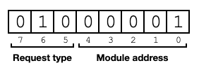
The first byte of a request is made up of the Piconet address of the module that the Nimbus wants to contact, and some flags identifying whether to read or write, and whether a virtual register or a data port are being addressed. The frame has the 9th bit set to 1 to signify an address. The request type flags are what the Nimbus Museum observes as:
more indepth communications with modules were started with a higher number, module 1, for example, would be addressed with address 65
Valid module addresses may range from 1 to 30 (01h-1Eh). The address occupies the lower 5 bits of the first byte of the request. Addresses 1-8 are normally given to serial modules representing DOS devices COM1-COM8. Addresses 9-16 are normally given to parallel modules representing DOS devices LPT1-LPT8.

Bit 5 set signifies a write. Bit 6 set (as above) signifies a read. Bit 7 set signifies that we are reading data from / writing data to the device attached to the module, rather than one of the module's control registers. (Bits 5 and 6 set together is an error. All three bits set, and all three bits clear, have other meanings.) Or alternatively:
000 - Status
1 byte request, 1 byte reply
The module, if present, will reply with one byte, its status register. This is the same thing you'll get from reading register 00h, except for when the timeout flag in bit 7 is cleared. More details in this article.
001 - Write register
3 byte request, 2 byte reply
The module will expect to receive two further bytes, without "bit 9" / the "address bit" set. The first is the address of a virtual register- this can range from 00h to 35h on the parallel module. Registers 00h-1Fh are common between module types. Registers with higher numbers are specific to a module type. This is followed by the byte to be written to that register.
After acting on the request, the module will usually reply by repeating the request type / address byte, followed by a status byte as above. In certain circumstances that I haven't yet fully decoded, writing to register 16h would not be acknowledged.
Bit 4 of the returned status byte will be set if an invalid register is requested.
010 - Read register
2 byte request, 3 byte reply
The module will expect to receive one further byte, again the address of a virtual register. It should reply with 3 bytes:
- The byte read from the register (will be 00h if an invalid register)
- Repeating the request type / address byte
- Status byte (with bit 4 set if an invalid register)
011 and 100 - Invalid
1 byte request, 0 byte reply
No further bytes are expected, and no bytes will be returned, but bit 4 of the status will be set next time it is read.
101 - Write data
2 byte request, 2 byte reply
Output a byte of data to the peripheral connected to the Piconet module. This data may be buffered. Expects one data byte. Should reply with the request type / address byte, followed by the status.
It is advised to check status bit 1 before making this request to see if the transmit buffer is currently full.
110 - Read data
1 byte request, 3 byte reply
Input a byte of data from the peripheral connected to the Piconet module. This data may be buffered. Expects no further bytes. Should reply with the data byte read, the request type / address byte, and the status.
It is advised to check status bit 0 before making this request to see if the receive buffer contains any data. The status you get back from this request reflects whether anything is still left in the buffer afterwards, not necessarily whether the data byte returned with this request is valid.
111 - Reset module
1 byte request, 0 byte reply
Restarts the Piconet module's firmware. No further bytes are expected for this request, and no bytes will be returned.
Comments